PVB Laminated Glass Machine
Laminated Glass Production Line
Table of Contents
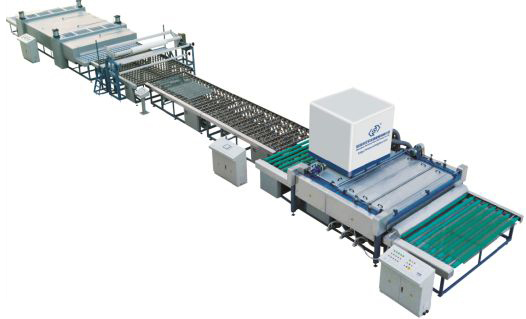
The PVB film laminated glass production line mainly consists of these parts: PVB film laying machine, assembly machine, pre-pressing machine, autoclave, and powder spraying machine.
1. PVB Film Laying Machine
The interlayer PVB film laying machine must meet the following equipment performance and work effectiveness standards:
1. The movement of PVB film during rotation should be smooth, flexible, safe, reliable, and free of vibration.
2. The parallelism tolerance of the PVB film laying machine shafts should be within 2mm.
3. The lifting and positioning of PVB film should be quick, safe, and easy.
4. The transmission reducer and motor should operate normally without vibration.
5. The equipment noise should be ≤85dB (A).
The working effectiveness of the interlayer PVB film laying machine is that the speed of PVB film should be smooth and uniform during stretching and releasing, and the machine should be flexible, safe, and reliable, with no foreign objects detached.
2. Assembly Machine
The laminated glass assembly machine is a device used in the production process of laminated glass to combine two or more glass sheets with PVB film and ensure their precise positioning. It consists of an assembly table and a transport suction cup hoist.
2.1 Mechanical requirements of the laminated glass assembly machine
① Positioning accuracy: the deviation between the overlapping glass sheets should meet the local standards.
② Walking and positioning accuracy of the suction cup rack should be ≤0.5mm.
③ Parallelism tolerance of the walking guide beam should be 3mm.
④ Planarity tolerance of the walking guide surface should be 2mm.
⑤ The vacuum pump should work normally, and the vacuum degree should be within the range of 0.05-0.09 MPa. When power is cut off, the suction time should be ≥20min.
⑥ The vacuum rubber suction cup should not leave any traces on the glass after suction.
⑦ The walking and lifting mechanisms should work smoothly, reliably, and without vibration.
⑧ The parallelism tolerance of the transfer silver should be 1mm.
⑨ The radial runout of the transfer roller should not exceed 1mm.
⑩ The equipment noise should be ≤85dB(A).
2.2 Performance requirements of the suction cup hoist for laminated glass assembly
① The deviation between the glass sheets after assembly should be <1mm.
② The repetitive positioning accuracy error of the automatic walking frame should be <1mm.
2.3 Preparations before starting the laminating machine
① Check that the equipment is clean and free of dust and lint.
② Check that the air pressure is between 0.5~0.8MPa.
③ Turn on the vacuum pump and check that the vacuum level is greater than 0.08 and the vacuum pump oil level is adequate.
④ Check that the vacuum suction cups are in the correct position for the glass to be laminated, and that the upper and lower suction cups are aligned properly and fixed firmly.
⑤ Check that the overload protection is in place.
2.4 Attention during the use of the laminating machine
① Check that the air pressure and vacuum level meet the requirements before laminating.
② Adjust the position of the suction cups according to the size of the glass to be laminated and fix them firmly.
③ Clean and tidy the laminating machine before laminating and ensure that it is qualified for use.
④ When laminating, place the glass properly and when the laminating machine lifts the upper glass, gently press down on the lower glass to prevent breakage.
⑤ After laminating, align the upper and lower glass, and cut the surrounding adhesive tape slightly larger than the glass.
⑥ When installing the glass with the adhesive ring, make sure it is properly installed to prevent air leakage during vacuum pumping.
⑦ When the arm is lifted with glass attached, do not place iron or other metal objects near the arm magnetic limit switch.
⑧ After the laminating is completed, the suction cups can be lifted directly to remove the glass.
⑨ After the laminating is completed, promptly turn off the vacuum pump, the laminating machine, and clean it. If necessary, turn off the compressed air source.
2.5 Operation of the laminating machine
① Turn on the main switch, lighting switch, and control switch in sequence.
② Place the glass on the lower suction cup holder according to the process requirements, step on the foot switch to make the laminating machine hold the glass and separate the glass.
③ After the glass is separated, use a vacuum cleaner to clean the inside surface of the glass, lay the adhesive tape according to the process requirements, and then step on the foot switch again to lower the arm and place the glass.
④ After the arm is lowered and the glass is placed, cut off the excess adhesive tape according to the process requirements, install the adhesive ring, step on the suction cup release (air blowing) switch, and lift the glass onto the vacuum pumping cart. Then proceed to laminate the next piece of glass using the above method.
3. Pre-pressing Machine
The pre-pressing machine for laminated glass is a device used in the processing of laminated glass to heat and mechanically press the interlayer to bond it.
3.1 Mechanical performance requirements of the pre-pressing machine
① The conveying structure should operate smoothly, be calculable, and have no vibration.
② The parallelism tolerance of the rear delivery roller should be 0.5mm.
③ The radial runout of the conveying roller should be no more than 0.5mm.
④ The alignment of the busbar on the conveying silver and the flatness tolerance should be 1mm.
⑤ The parallelism tolerance of the upper and lower silver pressure should be 0.5mm.
⑥ The noise of the entire machine should be ≤85dB(A).
3.2 Product pressing requirements of the pre-pressing machine
① The glass should have no defects such as air pockets or delamination after pressing.
② The deviation of the rear part of the glass after pre-pressing should be less than 0.5mm.
③ The glass should not collide or scratch during the conveying process in the furnace.
3.3 Operation of the pre-pressing machine
① Turn on the main switch and start the vacuum pump.
② According to the process requirements, connect the vacuum joint of the glass car to the outside vacuum pipe joint for cold drawing.
③ After cold drawing is completed, push the glass car into the cabinet and connect the vacuum pipe joint inside the cabinet to the trolley, then disconnect the outside vacuum pipe joint (cut off), and the next glass can be cold drawn outside the cabinet.
④ Close the cabinet door and turn on the circulating fan switch.
⑤ Adjust the temperature controller and timer on the operating panel according to the process requirements to determine the heating temperature and time.
⑥ Turn on the heating switch to heat the cabinet.
⑦ When the predetermined time and temperature are reached, the heating will automatically turn off, and the indicator light will be on.
⑧ Turn off the circulating fan, open the cabinet door, and push out the glass. The cold-drawn glass outside can be continuously produced by pushing it into the cabinet according to the above method.
3.4 Precautions when using the pre-pressing machine
① Before starting the machine, check that there are no flammable materials such as paper, wood, and oil in the cabinet.
② When starting the machine, check that the temperature controller is effective and preset the heating temperature and time.
③ When starting the machine, check that the vacuum degree meets the requirements and there is no leakage.
④ The glass should be cold-drawn first and then pushed into the cabinet for preheating and pre-pressing. When pushing into the cabinet, the vacuum pipe joint inside the cabinet should be connected first, and then the outside vacuum joint should be disconnected to avoid intermittent vacuuming.
⑤ When closing the cabinet door, check that there is no one inside.
⑥ Before turning on the heater, turn on the fan first, and before turning off the fan, turn off the heater first.
⑦ When pushing the trolley and closing the door, avoid the glass from colliding.
3.5 When adjusting the gap between the rolls of the laminated glass pre-pressing machine, the following aspects should be noted
② For the flat press with automatic gap adjustment device, the upper pressure roll should be lifted first, and then the gap between the rolls should be adjusted. For the flat press without automatic gap adjustment device, the pressure on the silver should be zero before adjusting the gap according to the thickness of the glass.
③ The gap between the silver and the glass should be slightly smaller than the actual total thickness of the glass, and the reduction value should meet the requirements.
④ After adjusting the gap between the rolls, it is necessary to confirm that the total thickness of the glass corresponds to the gap before the glass can be fed into the machine.
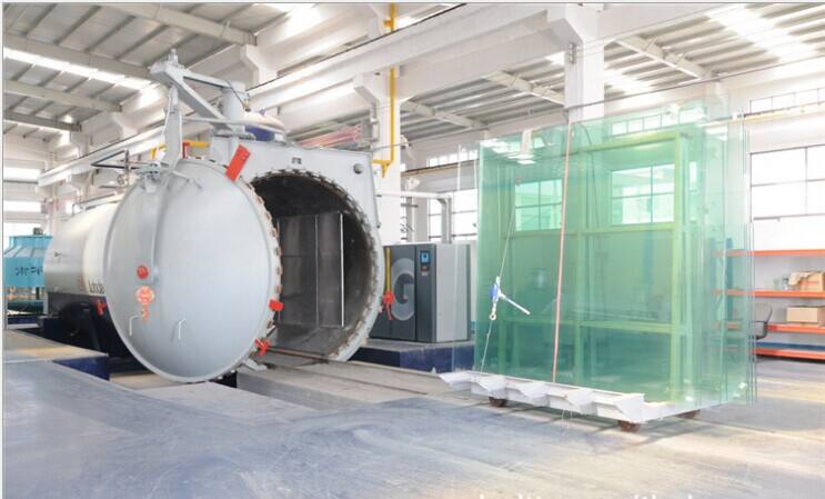
4. Autoclave
A laminated glass autoclave is a specialized device used for the final heating and pressure treatment of laminated glass after pre-pressing.
4.1 Structure and functions of each part of the autoclave
The laminated glass autoclave is mainly composed of a kettle body device, a cover device, a swinging device, a hand-cranked reducer, safety devices, supports, insulation layer, sealing device, pipeline valves and instruments, etc. The auxiliary parts include drainage devices.
① Kettle body device It is mainly composed of a cylinder and a kettle body flange welded together. 44 teeth are evenly distributed along the flange circumference and correspondingly mesh with the 44 teeth on the kettle cover flange. A track is laid on the bottom of the kettle to allow a steam-curing trolley to move or park. Various pipe supports and connections are arranged on the outside of the kettle body for steam inlet and outlet, discharge of condensed water and installation of various instruments and valves.
② Cover device It is mainly composed of a kettle cover flange, gear plate, and hemispherical head welded together. The cover is suspended by a handle and a short shaft and meshed with the kettle body flange to close the autoclave.
③ Swinging device It is mainly composed of a shaft, a cantilever beam, a support plate, a pull plate, and a pull rod. It is installed at the top of the kettle end and connected to the kettle cover handle through the pull rod to suspend and rotate the autoclave.
④ Hand-cranked reducer It is fixed on the side of the kettle body flange and mainly consists of a pair of turbine pairs and a pair of bevel gear shafts. The gear plate is driven by the gear to rotate the kettle cover around the center, allowing the teeth of the kettle body and the kettle cover flange to mesh or disengage.
⑤ Safety devices It is fixed on the side of the kettle body flange and consists of a safety handle, a seat, a connecting rod, and a ball valve. When the kettle cover is closed, the safety handle is turned to the horizontal position, locking the kettle cover to prevent it from opening, and the exhaust ball valve is closed accordingly. When opening the cover, first make the safety handle vertical, and then the ball valve will open. After the remaining steam in the kettle is discharged through the ball valve, the kettle cover can be opened to avoid danger.
⑥ Supports are used to support the kettle body, consisting of a middle support and end supports. Except for the fixed middle support, the other supports can move along the axis of the kettle body with the help of rolling elements to adapt to the expansion and contraction of the kettle body.
⑦ Insulation layer It mainly consists of insulation materials, skeleton, and protective panels, etc., to prevent heat loss during the use of the autoclave.
⑧ Sealing device It consists of a sealing ring, a stop valve, and an inlet bend, etc. The sealing ring is embedded in the sealing groove of the kettle body flange. During the pressurization stage, steam from an external source enters the sealing groove through the bend and valve, pressurizes the sealing ring at the kettle cover end face, and after reaching the rated pressure, seals by relying on the air pressure of the kettle body itself.
⑨ Instrumentation Includes pressure gauges, temperature gauges, safety nets, thermistors, ball valves, etc., to ensure the safe use of the autoclave.
⑩ Drainage device It is used to discharge condensed water and consists of drainage devices, steam traps, and discharge screens, etc. The water collection cylinder is connected to the bottom
4.2 Performance requirements of the autoclave:
① Electrical performance:
a. The graphic, text and digital displays on the screen or monitor should be clear, complete and reliable.
b. The operation keys on the control panel should be sensitive, reliable, and accurate.
c. The travel, limit switches and electrical interlocking devices should be sensitive and accurate.
d. All electrical circuits should be placed in wire ducts, wired accurately, and labeled.
e. The insulation resistance of the equipment should be ≥0.5MQ.
② Mechanical performance:
a. The autoclave door should open flexibly and without obstruction.
b. The fan should operate normally and without abnormal noise.
c. The cooling water pump should operate normally and without abnormal noise.
d. All pneumatic pipeline welding should be intact and reliable, and the pneumatic gate should operate accurately and smoothly.
e. The noise level of the equipment should be ≤85dB(A).
③ Sealing performance:
a. The sealing ring gasket should be flat without any protrusions or convexities.
b. The asbestos sealing packing should be compacted to ensure tightness without any gaps.
4.3 Test run of the empty autoclave, the operating procedures for the empty test run are as follows:
① Before the test run, check strictly whether the connecting nuts are tightened, whether the safety accessories are intact and in working condition, whether the movable parts of the support are flexible and smooth, and whether the drainage system is normal.
② Raise the pressure to the design pressure during the test run. If the safety net cannot exhaust normally, adjust it accordingly.
③ Lower the pressure to the working pressure and maintain it for 30 minutes, comprehensively inspect the pressurized components and connecting pipelines, focusing on leakages, pressure gauges, safety valves, and the temperature difference between the upper and lower walls. If any abnormal phenomena are found, immediately reduce the pressure and conduct inspections until normal operation is achieved.
4.4 Autoclave Safe Operating Procedures
① When operating the autoclave, ensure that the safety accessories are complete, sensitive, reliable, and conduct regular inspections at fixed points. If any abnormal conditions are found, reduce the pressure and handle them promptly.
② Close the inlet mesh, drain valve, and mesh gates a1, a2, and a3 before pressurizing.
③ Apply graphite powder lubricant to the exposed outer surface of the closure loop.
④ Close the autoclave cover device, shake the reducer, rotate the autoclave cover to ensure complete meshing with the autoclave body flange teeth, and turn the safety handle to the horizontal position to lock the cover.
⑤ Open valves a1 and a3 to allow the main steam to seal the autoclave cover end face.
⑥ After opening the inlet valve to the working pressure, open valve a2 and close valve a3 to rely on the working steam inside the autoclave to self-seal.
⑦ After the steam treatment is complete, open the drain valve. Only when the pressure gauge indicates zero can the safety handle be turned to the vertical position to vent any remaining gas in the autoclave through the ball net. Then, shake the reducer and slow down the speed when the autoclave cover flange teeth are near the intersection of the meshing steps, and stop rotating when the teeth on all sides contact the autoclave body flange teeth. At this time, the autoclave cover end face has separated from the sealing ring, and it is confirmed that there is no residual gas before the autoclave cover is turned back to the inner side of the autoclave body. During the autoclave opening process, the operator should be on the right side of the autoclave cover, and no one should be in front of the autoclave cover.
⑧ When opening and closing the autoclave cover and the trolley enters and exits the autoclave body, do it slowly and carefully to avoid colliding with the autoclave body.
⑨ During the pressure rise and stabilization process, frequently monitor the condensate water level. When the water level approaches the lowest point of the autoclave body or when there is a water level alarm, it indicates that the automatic drainage volume of the water supply device is not enough, and the drain valve needs to be opened for manual drainage. At the same time, monitor the upper and lower wall temperatures. If they exceed 40°C, strengthen the drainage, and perform regular drainage before and after each autoclave treatment.
⑩ It is strictly prohibited to operate the autoclave beyond its rated temperature and pressure limits.
5. Powder Spraying Machine
In order to ensure that the two pieces of laminated glass have the same shape during hot bending, both pieces of glass need to be bent together on the mold. However, when the two pieces of glass are stacked together, it is easy to produce scratches, adhesion during hot bending, and difficulty in separating during lamination. Therefore, before hot bending, a thin layer of powder is evenly sprayed on the bonding surface of the glass. This not only prevents surface scratching during bonding but also makes it easier to separate during lamination. At the same time, it also prevents the glass from sticking together during hot bending, making it easier for the glass to slide slightly during the forming process.
The criteria for judging whether the powder spraying is qualified are: there should be powder on the glass surface, but not too thick; there should be no lumps or uneven distribution on the sprayed surface. A qualified powder spraying surface should be thin, evenly distributed, and without lumps.
The powder spraying machine is a device that installs the powder box on a horizontal transmission roller or directly on the horizontal output platform of a washing and drying machine. There is a powder receiving box under the powder box, and a dust removal device on top. The powder box and the powder receiving box only have gaps for the transmission rollers and the glass to pass through. The powder spraying machine uses electromagnetic or other methods to vibrate and feed the extremely fine powder into the nozzle. Under the action of compressed air, the powder is sprayed into the powder box and then evenly sprinkled on the glass surface passing through the powder box due to its own weight.
When the powder spraying machine is started, it must be operated according to the specified operating procedures, as follows:
1. Check whether the vibrator powder box has been filled with dry and qualified silicon powder.
2. Check whether the compressed air filter, oil and water separator, and moisture absorption device are effective.
3. Check that the air pressure meets the requirements (0.5~0.8MPa).
4. Start the exhaust fan for dust removal and check that the powder receiving box is in place.
5. Turn on the powder spraying switch, start the vibrator, and begin powder spraying.
6. Feed the glass, adjust the powder spraying air pressure to ensure that the powder thickness is qualified.
7. Release the glass for powder spraying production.
Contact us today to learn more about our PVB laminating film and how we can help meet your needs.